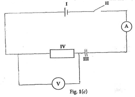
Fig. 1(c) is an electric circuit diagram
Study it carefully and answer the questions that follow
(i)
State one function for each of the parts labelled I, II, III and IV.
(ii)
If the voltmeter reads 2.4 V and the ammeter reads 0.8 A when the circuit is closed, calculate the value of the part labelled IV.
(iii)
State one way of conserving the value of the part labelled I in the circuit.
(iv)
State two observations that can be made when the circuit is closed.
i)
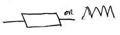
Draw the symbols for each of the following electronic components:
α)
Resistor;
β)
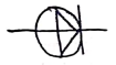
(p-n junction) diode;
γ)
Cell;
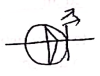
δ)
Light Emitting Diode / LED.
ii)
Use the symbols drawn in (i) together with a switch to draw a circuit diagram to demonstrate forward biasing of a (p-n junction) diode and the light emitting diode.
iii)
State the effect of the resistor on the (p-n junction) diode and the light emitting diode when the circuit is closed.
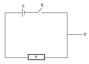
The diagram below is used to demonstrate an activity in the laboratory.
Study it carefully and use it to answer the questions that follow:
(i)
What does the diagram represent?
(ii)
Identify the components labelled, D, E, K and P in the diagram.
(iii)
State one function each of the parts labelled, D, E, K and P.
(iv)
Mention the energy transformation that occurs in E in the diagram when K is closed.
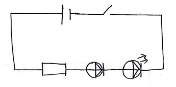
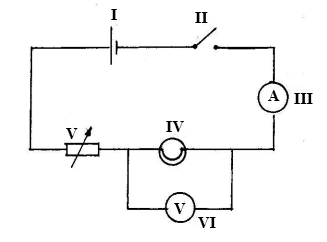
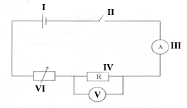
Study the simple circuit diagram shown below and answer the questions that follow.
(i)
Identify the components labelled I, II, III, IV, V and VI
(ii)
Which component is used to close the circuit?
(iii)
State the observation that will be made when the circuit is closed.
(iv)
State the energy transformations that take place when the circuit is closed
(v)
Give the name of the circuit connection between components IV and VI
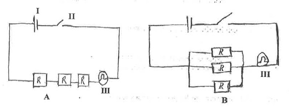
The diagrams below are illustrations of electrical circuits.
Study the diagram carefully and answer the questions that follow.
(i)
Identify each of the components labelled I, II and III.
(ii)
State the type of arrangement of resistors (R) in B.
(iii)
State the effect of the arrangement of resistors in each of the diagrams A and B on III.
(iv)
Give a reason for each of the answers stated in (iii).
The diagram below are illustrations of an experimental set-up. Study the diagrams carefully and answer the questions that follow.
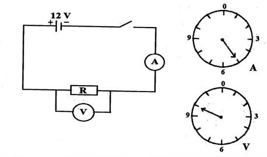
(i)
Name the measuring instrument that is in:
(α)
parallel;
(β)
series;
With the resistor R
(ii)
What quantity does each of the named instruments in (i) measure?
(iii)
Read and record the values as indicated on:
(α)
A in amperes;
(β)
V in volts.
(iv)
Use the values read in (iii) to calculate the value of R.
(v)
State one precaution to be taken in performing this experiment.
The diagram below is an illustration of an electrical circuit.
Study the diagram carefully and answer the questions that follow.
i)
Name each of the parts labelled I, II, IV, VI.
ii)
State the energy transformation that takes place in:
α)
I
β)
IV
iii)
State the S.I units of the quantity measured by each of the parts labelled:
α)
III
β)
V
iv)
State the function of the part labelled VI.


Digital Address: GZ-033-0057
King Kotey Road
Teshie - Accra
Ghana
+233 59 993 7122
Finland
+358 44 986 0934
info@kuulchat.com
![]()
© Copyright 2015 - 2025
All Rights Reserved